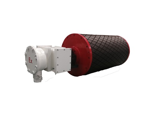
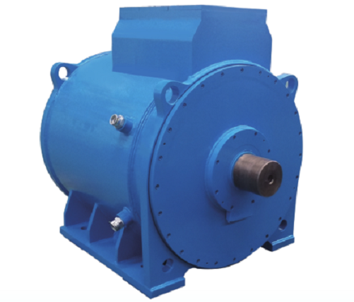
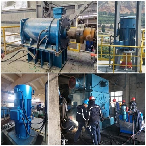
In recent years, permanent magnet direct drive motors have made significant progress and are mainly used in low-speed loads, such as belt conveyors, mixers, wire drawing machines, low-speed pumps, replacing electromechanical systems composed of high-speed motors and mechanical reduction mechanisms. The speed range of the motor is generally below 500rpm. Permanent magnet direct drive motors can be mainly divided into two structural forms: external rotor and internal rotor. External rotor permanent magnet direct drive is mainly used in belt conveyors.
In the design and application of permanent magnet direct drive motors, it should be noted that permanent magnet direct drive is not suitable for particularly low output speeds. When most loads within 50r/min are driven by a direct drive motor, if the power remains constant, it will result in a large torque, leading to high motor costs and reduced efficiency. When the power and speed are determined, it is necessary to compare the economic efficiency of the combination of direct drive motors, higher speed motors, and gears (or other speed increasing and decreasing mechanical structures). At present, wind turbines above 15MW and below 10rpm are gradually adopting a semi direct drive scheme, using gears to appropriately increase motor speed, reduce motor costs, and ultimately lower system costs. The same applies to electric motors. Therefore, when the speed is below 100 r/min, economic considerations should be carefully considered, and a semi direct drive scheme can be chosen.
Permanent magnet direct drive motors generally use surface mounted permanent magnet rotors to increase torque density and reduce material usage. Due to the low rotational speed and small centrifugal force, it is not necessary to use a built-in permanent magnet rotor structure. Generally, pressure bars, stainless steel sleeves, and fiberglass protective sleeves are used to fix and protect the rotor permanent magnet. However, some motors with high reliability requirements, relatively small pole numbers, or high vibrations also use built-in permanent magnet rotor structures.
The low-speed direct drive motor is driven by a frequency converter. When the pole number design reaches an upper limit, further reduction in speed will result in a lower frequency. When the frequency of the frequency converter is low, the duty cycle of PWM decreases, and the waveform is poor, which can lead to fluctuations and unstable speed. So the control of particularly low speed direct drive motors is also quite difficult. At present, some ultra-low speed motors adopt a magnetic field modulation motor scheme to use a higher driving frequency.
Low speed permanent magnet direct drive motors can mainly be air-cooled and liquid cooled. Air cooling mainly adopts the IC416 cooling method of independent fans, and liquid cooling can be water cooling (IC71W), which can be determined according to the on-site conditions. In liquid cooling mode, the heat load can be designed higher and the structure more compact, but attention should be paid to increasing the thickness of the permanent magnet to prevent overcurrent demagnetization.
For low-speed direct drive motor systems with requirements for speed and position accuracy control, it is necessary to add position sensors and adopt a control method with position sensors; In addition, when there is a high torque requirement during startup, a control method with a position sensor is also required.
Although the use of permanent magnet direct drive motors can eliminate the original reduction mechanism and reduce maintenance costs, an unreasonable design can lead to high costs for permanent magnet direct drive motors and a decrease in system efficiency. Generally speaking, increasing the diameter of permanent magnet direct drive motors can reduce the cost per unit torque, so direct drive motors can be made into a large disk with a larger diameter and shorter stack length. However, there are also limits to the increase in diameter. An excessively large diameter can increase the cost of the casing and shaft, and even the structural materials will gradually exceed the cost of effective materials. So designing a direct drive motor requires optimizing the length to diameter ratio to reduce the overall cost of the motor.
Finally, I would like to emphasize that permanent magnet direct drive motors are still frequency converter driven motors. The power factor of the motor affects the current on the output side of the frequency converter. As long as it is within the capacity range of the frequency converter, the power factor has a small impact on performance and will not affect the power factor on the grid side. Therefore, the power factor design of the motor should strive to ensure that the direct drive motor operates in MTPA mode, which generates maximum torque with the minimum current. The important reason is that the frequency of direct drive motors is generally low, and the iron loss is much lower than the copper loss. Using MTPA method can minimize the copper loss. Technicians should not be influenced by traditional grid connected asynchronous motors, and there is no basis for judging the efficiency of the motor based on the current magnitude on the motor side.
Anhui Mingteng Permanent-Magnetic Machinery &Electrical Equipment Co., Ltd is a modern high-tech enterprise that integrates the research and development, manufacturing, sales, and service of permanent magnet motors. The product variety and specifications are complete. Among them, low-speed direct drive permanent magnet motors (7.5-500rpm) are widely used in industrial load such as fans, belt conveyors, plunger pumps, and mills in cement, building materials, coal mines, petroleum, metallurgy, and other industries, with good operating conditions.
Post time: Jan-18-2024


