I. The purpose and significance of measuring synchronous inductance
(1)Purpose of Measuring the Parameters of Synchronous Inductance (i.e. Cross-axis Inductance)
The AC and DC inductance parameters are the two most important parameters in a permanent magnet synchronous motor. Their accurate acquisition is the prerequisite and foundation for motor characteristic calculation, dynamic simulation and speed control. The synchronous inductance can be used to calculate many steady-state properties such as power factor, efficiency, torque, armature current, power and other parameters. In the control system of permanent magnet motor using vector control, the synchronous inductor parameters are directly involved in the control algorithm, and the research results show that in the weak magnetic region, the inaccuracy of the motor parameters can lead to a significant reduction of torque and power. This shows the importance of synchronous inductor parameters.
(2)Problems to be noted in measuring synchronous inductance
In order to obtain a high power density, the structure of permanent magnet synchronous motors is often designed to be more complex, and the magnetic circuit of the motor is more saturated, which results in the synchronous inductance parameter of the motor varying with the saturation of the magnetic circuit. In other words, the parameters will change with the operating conditions of the motor, completely with the rated operating conditions of the synchronous inductance parameters can not accurately reflect the nature of the motor parameters. Therefore, it is necessary to measure the inductance values under different operating conditions.
2.permanent magnet motor synchronous inductance measurement methods
This paper collects various methods of measuring synchronous inductance and makes a detailed comparison and analysis of them. These methods can be roughly categorized into two main types: direct load test and indirect static test. Static testing is further divided into AC static testing and DC static testing. Today, the first installment of our "Synchronous Inductor Test Methods" will explain the load test method.
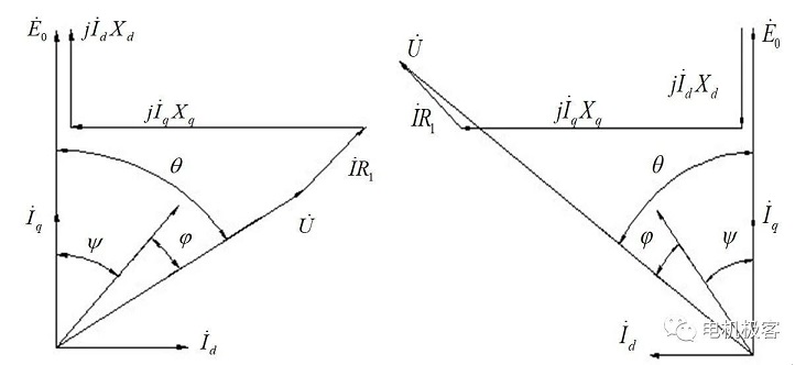
Literature [1] introduces the principle of direct load method. Permanent magnet motors can usually be analyzed by using the double reaction theory to analyze their load operation, and the phase diagrams of generator and motor operation are shown in Figure 1 below. The power angle θ of the generator is positive with E0 exceeding U, the power factor angle φ is positive with I exceeding U, and the internal power factor angle ψ is positive with E0 exceeding I. The power angle θ of the motor is positive with U exceeding E0, the power factor angle φ is positive with U exceeding I, and the internal power factor angle ψ is positive with I exceeding E0.

Fig. 1 Phase diagram of permanent magnet synchronous motor operation
(a)Generator state (b) Motor state
According to this phase diagram can be obtained: when the permanent magnet motor load operation, measured no-load excitation electromotive force E0, armature terminal voltage U, current I, power factor angle φ and power angle θ and so on, can be obtained armature current of the straight axis, cross-axis component Id = Isin (θ - φ) and Iq = Icos (θ - φ), then Xd and Xq can be obtained from the following equation:
When the generator is running:
Xd=[E0-Ucosθ-IR1cos(θ-φ)]/Id (1)
Xq=[Usinθ+IR1sin(θ-φ)]/Iq (2)
When the motor is running:
Xd=[E0-Ucosθ+IR1cos(θ-φ)]/Id (3)
Xq=[Usinθ-IR1sin(θ-φ)]/Iq (4)
The steady state parameters of permanent magnet synchronous motors change as the operating conditions of the motor change, and when the armature current changes, both Xd and Xq change. Therefore, when determining the parameters, be sure to also indicate the motor operating conditions. (Amount of alternating and direct shaft current or stator current and internal power factor angle)
The main difficulty when measuring the inductive parameters by the direct load method lies in the measurement of the power angle θ. As we know, it is the phase angle difference between the motor terminal voltage U and the excitation electromotive force. When the motor is running stably, the end voltage can be obtained directly, but E0 cannot be obtained directly, so it can only be obtained by an indirect method to obtain a periodic signal with the same frequency as E0 and a fixed phase difference to replace E0 in order to make a phase comparison with the end voltage.
The traditional indirect methods are:
1) in the armature slot of the motor under test buried pitch and the motor's original coil of several turns of fine wire as a measuring coil, in order to obtain the same phase with the motor winding under test voltage comparison signal, through the comparison of the power factor angle can be obtained.
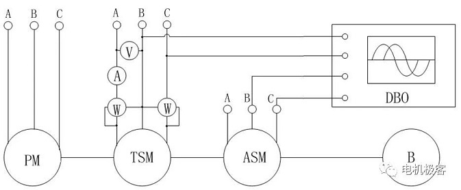
2) Install a synchronous motor on the shaft of the motor under test that is identical to the motor under test. The voltage phase measurement method [2], which will be described below, is based on this principle. The experimental connection diagram is shown in Figure 2. The TSM is the permanent magnet synchronous motor under test, the ASM is an identical synchronous motor that is additionally required, the PM is the prime mover, which can be either a synchronous motor or a DC motor, B is the brake, and the DBO is a dual beam oscilloscope.The phases B and C of the TSM and ASM are connected to the oscilloscope. When the TSM is connected to a three-phase power supply, the oscilloscope receives the signals VTSM and E0ASM. because the two motors are identical and rotate synchronously, the no-load backpotential of the TSM of the tester and the no-load backpotential of the ASM, which acts as a generator, E0ASM, are in phase. Therefore, the power angle θ, i.e., the phase difference between VTSM and E0ASM can be measured.
Fig. 2 Experimental wiring diagram for measuring power angle
This method is not very commonly used, mainly because: ① in the rotor shaft mounted small synchronous motor or rotary transformer required to be measured motor has two shaft outstretched end, which is often difficult to do. ② The accuracy of the power angle measurement depends largely on the high harmonic content of the VTSM and E0ASM, and if the harmonic content is relatively large, the accuracy of the measurement will be reduced.
3) To improve the power angle test accuracy and ease of use, now more use of position sensors to detect the rotor position signal, and then phase comparison with the end voltage approach
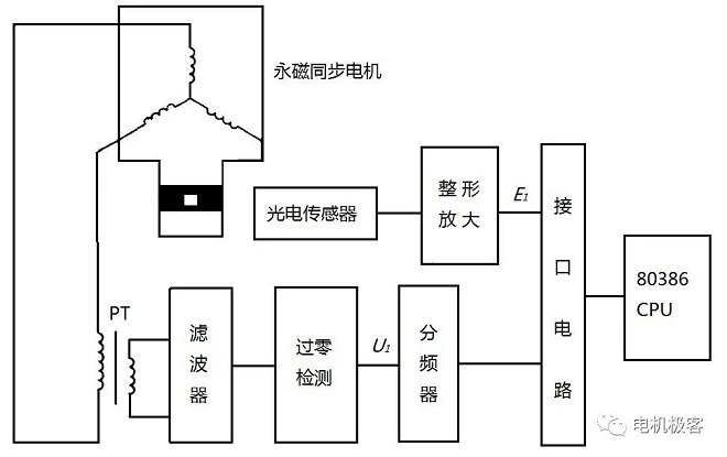
The basic principle is to install a projected or reflected photoelectric disk on the shaft of the measured permanent magnet synchronous motor, the number of uniformly distributed holes on the disk or black and white markers and the number of pairs of poles of the synchronous motor under test. When the disk rotates one revolution with the motor, the photoelectric sensor receives p rotor position signals and generates p low voltage pulses. When the motor is running synchronously, the frequency of this rotor position signal is equal to the frequency of the armature terminal voltage, and its phase reflects the phase of the excitation electromotive force. The synchronization pulse signal is amplified by shaping, phase shifted and the test motor armature voltage for phase comparison to get the phase difference. Set when the motor no-load operation, the phase difference is θ1 (approximate that at this time the power angle θ = 0), when the load is running, the phase difference is θ2, then the phase difference θ2 - θ1 is the measured permanent magnet synchronous motor load power angle value. The schematic diagram is shown in Figure 3.
Fig. 3 Schematic diagram of power angle measurement
As in the photoelectric disk uniformly coated with black and white mark is more difficult, and when the measured permanent magnet synchronous motor poles at the same time marking disk can not be common with each other. For simplicity, can also be tested in the permanent magnet motor drive shaft wrapped in a circle of black tape, coated with a white mark, the reflective photoelectric sensor light source emitted by the light gathered in this circle on the surface of the tape. In this way, every turn of the motor, photoelectric sensor in the photosensitive transistor due to receive a reflected light and conduction once, resulting in an electrical pulse signal, after amplification and shaping to get a comparison signal E1. from the test motor armature winding end of any two-phase voltage, by the voltage transformer PT down to a low voltage, sent to the voltage comparator, the formation of a representative of the rectangular phase of the voltage pulse signal U1. U1 by the p-division frequency, the phase comparator comparison to get a comparison between the phase and the phase comparator. U1 by the p-division frequency, by the phase comparator to compare its phase difference with the signal.
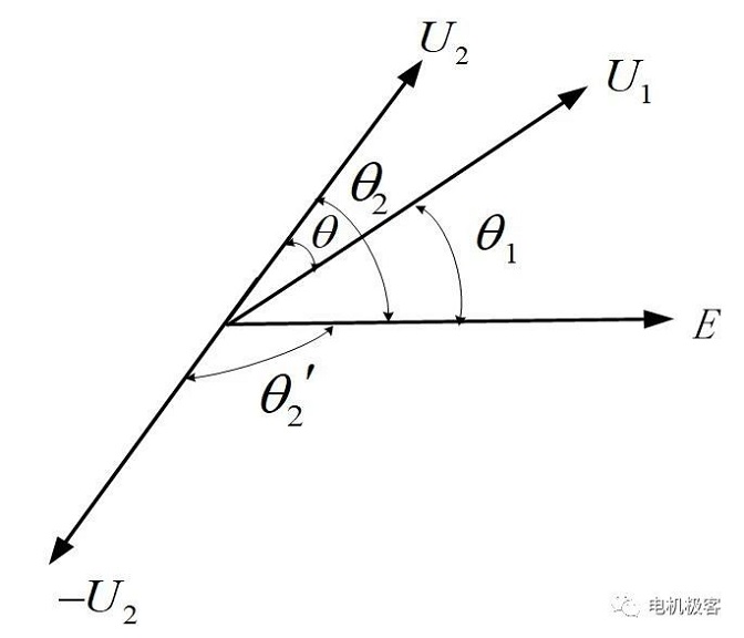
The shortcoming of the above power angle measurement method is that the difference between the two measurements should be made to obtain the power angle. In order to avoid the two quantities subtracted and reduce the accuracy, in the measurement of the load phase difference θ2, the U2 signal reversal, the measured phase difference is θ2'=180 ° - θ2, the power angle θ=180 ° - (θ1 + θ2'), which converts the two quantities from the subtraction of the phase to the addition. The phase quantity diagram is shown in Fig. 4.
Fig. 4 Principle of phase addition method for calculating phase difference
Another improved method does not use the voltage rectangular waveform signal frequency division, but use a microcomputer to simultaneously record the signal waveform, respectively, through the input interface, record the no-load voltage and rotor position signal waveforms U0, E0, as well as the load voltage and rotor position rectangular waveform signals U1, E1, and then move the waveforms of the two recordings relative to each other until the waveforms of two voltage rectangular waveform signals are completely overlapped, when the phase difference between the two rotor The phase difference between the two rotor position signals is the power angle; or move the waveform to the two rotor position signal waveforms coincide, then the phase difference between the two voltage signals is the power angle.
It should be pointed out that the actual no-load operation of permanent magnet synchronous motor, the power angle is not zero, especially for small motors, due to no-load operation of no-load loss (including stator copper loss, iron loss, mechanical loss, stray loss) is relatively large, if you think that the no-load power angle of zero, it will cause a large error in the measurement of the power angle, which can be used to make the DC motor running in the state of the motor, the direction of the steering and the test motor steering consistent, with the DC motor steering, the DC motor can run on the same state, and the DC motor can be used as a test motor. This can make the DC motor running in the motor state, the steering and the test motor steering consistent with the DC motor to provide all the shaft loss of the test motor (including iron loss, mechanical loss, stray loss, etc.). The method of judgment is that the test motor input power is equal to the stator copper consumption, that is, P1 = pCu, and the voltage and current in phase. This time the measured θ1 corresponds to the power angle of zero.
Summary: the advantages of this method:
① The direct load method can measure the steady state saturation inductance under various load states, and does not require a control strategy, which is intuitive and simple.
Because the measurement is made directly under load, the saturation effect and the influence of demagnetization current on the inductance parameters can be taken into account.
Disadvantages of this method:
① The direct load method needs to measure more quantities at the same time (three-phase voltage, three-phase current, power factor angle, etc.), the measurement of the power angle is more difficult, and the accuracy of the test of each quantity has a direct impact on the accuracy of parameter calculations, and all kinds of errors in the parameter test are easy to accumulate. Therefore, when using the direct load method to measure the parameters, attention should be paid to the error analysis, and select a higher accuracy of the test instrument.
② The value of the excitation electromotive force E0 in this measurement method is directly replaced by the motor terminal voltage at no load, and this approximation also brings inherent errors. Because, the operating point of the permanent magnet changes with the load, which means that at different stator currents, the permeability and flux density of the permanent magnet are different, so the resulting excitation electromotive force is also different. In this way, it is not very accurate to replace the excitation electromotive force under load condition with the excitation electromotive force at no load.
References
[1] Tang Renyuan et al. Modern permanent magnet motor theory and design. Beijing: Machinery Industry Press. March 2011
[2] J.F. Gieras, M. Wing. Permanent Magnet Motor Technology, Design and Applications,2nd ed. New York: Marcel Dekker, 2002:170~171
Copyright: This article is a reprint of the WeChat public number motor peek(电机极客), the original link https://mp.weixin.qq.com/s/Swb2QnApcCWgbLlt9jMp0A
This article does not represent our company's views. If you have different opinions or views, please correct us!
Post time: Jul-18-2024


