Frequency converter is a technology that should be mastered when doing electrical work. Using frequency converter to control motor is a common method in electrical control; some also require proficiency in their use.
1.First of all, why use a frequency converter to control a motor?
The motor is an inductive load, which hinders the change of current and will produce a large change in current when starting.
The inverter is an electric energy control device that uses the on-off function of power semiconductor devices to convert the industrial frequency power supply into another frequency. It is mainly composed of two circuits, one is the main circuit (rectifier module, electrolytic capacitor and inverter module), and the other is the control circuit (switching power supply board, control circuit board).
In order to reduce the starting current of the motor, especially the motor with higher power, the greater the power, the greater the starting current. Excessive starting current will bring a greater burden to the power supply and distribution network. The frequency converter can solve this starting problem and allow the motor to start smoothly without causing excessive starting current.
Another function of using a frequency converter is to adjust the speed of the motor. In many cases, it is necessary to control the speed of the motor to obtain better production efficiency, and frequency converter speed regulation has always been its biggest highlight. The frequency converter controls the motor speed by changing the frequency of the power supply.
2.What are the inverter control methods?
The five most commonly used methods of inverter control motors are as follows:
A. Sinusoidal Pulse Width Modulation (SPWM) control method
Its characteristics are simple control circuit structure, low cost, good mechanical hardness, and can meet the smooth speed regulation requirements of general transmission. It has been widely used in various fields of the industry.
However, at low frequencies, due to the low output voltage, the torque is significantly affected by the stator resistance voltage drop, which reduces the maximum output torque.
In addition, its mechanical characteristics are not as strong as those of DC motors, and its dynamic torque capacity and static speed regulation performance are not satisfactory. In addition, the system performance is not high, the control curve changes with the load, the torque response is slow, the motor torque utilization rate is not high, and the performance decreases at low speed due to the existence of stator resistance and inverter dead zone effect, and the stability deteriorates. Therefore, people have studied vector control variable frequency speed regulation.
B. Voltage Space Vector (SVPWM) Control Method
It is based on the overall generation effect of the three-phase waveform, with the purpose of approaching the ideal circular rotating magnetic field trajectory of the motor air gap, generating a three-phase modulation waveform at a time, and controlling it in the way of inscribed polygon approximating the circle.
After practical use, it has been improved, that is, introducing frequency compensation to eliminate the error of speed control; estimating the flux amplitude through feedback to eliminate the influence of stator resistance at low speed; closing the output voltage and current loop to improve dynamic accuracy and stability. However, there are many control circuit links, and no torque adjustment is introduced, so the system performance has not been fundamentally improved.
C. Vector control (VC) method
The essence is to make the AC motor equivalent to a DC motor, and independently control the speed and magnetic field. By controlling the rotor flux, the stator current is decomposed to obtain the torque and magnetic field components, and the coordinate transformation is used to achieve orthogonal or decoupled control. The introduction of the vector control method is of epoch-making significance. However, in practical applications, since the rotor flux is difficult to accurately observe, the system characteristics are greatly affected by the motor parameters, and the vector rotation transformation used in the equivalent DC motor control process is relatively complex, making it difficult for the actual control effect to achieve the ideal analysis result.
D. Direct Torque Control (DTC) Method
In 1985, Professor DePenbrock of Ruhr University in Germany first proposed direct torque control frequency conversion technology. This technology has largely solved the shortcomings of the above-mentioned vector control, and has been rapidly developed with novel control ideas, concise and clear system structure, and excellent dynamic and static performance.
At present, this technology has been successfully applied to high-power AC transmission traction of electric locomotives. Direct torque control directly analyzes the mathematical model of AC motors in the stator coordinate system and controls the magnetic flux and torque of the motor. It does not need to equate AC motors to DC motors, thus eliminating many complex calculations in vector rotation transformation; it does not need to imitate the control of DC motors, nor does it need to simplify the mathematical model of AC motors for decoupling.
E. Matrix AC-AC control method
VVVF frequency conversion, vector control frequency conversion, and direct torque control frequency conversion are all types of AC-DC-AC frequency conversion. Their common disadvantages are low input power factor, large harmonic current, large energy storage capacitor required for DC circuit, and regenerative energy cannot be fed back to the power grid, that is, it cannot operate in four quadrants.
For this reason, matrix AC-AC frequency conversion came into being. Since matrix AC-AC frequency conversion eliminates the intermediate DC link, it eliminates the large and expensive electrolytic capacitor. It can achieve a power factor of 1, a sinusoidal input current and can operate in four quadrants, and the system has a high power density. Although this technology is not yet mature, it still attracts many scholars to conduct in-depth research. Its essence is not to indirectly control current, magnetic flux and other quantities, but to directly use torque as the controlled quantity to achieve it.
3.How does a frequency converter control a motor? How are the two wired together?
The wiring of the inverter to control the motor is relatively simple, similar to the wiring of the contactor, with three main power lines entering and then outgoing to the motor, but the settings are more complicated, and the ways to control the inverter are also different.
First of all, for the inverter terminal, although there are many brands and different wiring methods, the wiring terminals of most inverters are not much different. Generally divided into forward and reverse switch inputs, used to control the forward and reverse start of the motor. Feedback terminals are used to feedback the operating status of the motor,including operating frequency, speed, fault status, etc.
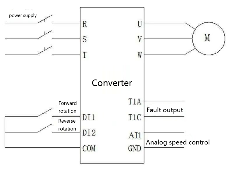
For speed setting control, some frequency converters use potentiometers, some use buttons directly, all of which are controlled through physical wiring. Another way is to use a communication network. Many frequency converters now support communication control. The communication line can be used to control the start and stop, forward and reverse rotation, speed adjustment, etc. of the motor. At the same time, feedback information is also transmitted through communication.
4.What happens to the output torque of a motor when its rotational speed (frequency) changes?
The starting torque and maximum torque when driven by a frequency converter are smaller than when driven directly by a power supply.
The motor has a large starting and acceleration impact when powered by a power supply, but these impacts are weaker when powered by a frequency converter. Direct starting with a power supply will generate a large starting current. When a frequency converter is used, the output voltage and frequency of the frequency converter are gradually added to the motor, so the motor starting current and impact are smaller. Usually, the torque generated by the motor decreases as the frequency decreases (speed decreases). The actual data of the reduction will be explained in some frequency converter manuals.
The usual motor is designed and manufactured for a 50Hz voltage, and its rated torque is also given within this voltage range. Therefore, speed regulation below the rated frequency is called constant torque speed regulation. (T=Te, P<=Pe)
When the output frequency of the frequency converter is greater than 50Hz, the torque generated by the motor decreases in a linear relationship inversely proportional to the frequency.
When the motor runs at a frequency greater than 50Hz, the size of the motor load must be considered to prevent insufficient motor output torque.
For example, the torque generated by the motor at 100Hz is reduced to about 1/2 of the torque generated at 50Hz.
Therefore, speed regulation above the rated frequency is called constant power speed regulation. (P=Ue*Ie).
5.Application of frequency converter above 50Hz
For a specific motor, its rated voltage and rated current are constant.
For example, if the rated values of the inverter and motor are both: 15kW/380V/30A, the motor can operate above 50Hz.
When the speed is 50Hz, the output voltage of the inverter is 380V and the current is 30A. At this time, if the output frequency is increased to 60Hz, the maximum output voltage and current of the inverter can only be 380V/30A. Obviously, the output power remains unchanged, so we call it constant power speed regulation.
What is the torque like at this time?
Because P=wT(w; angular velocity, T: torque), since P remains unchanged and w increases, the torque will decrease accordingly.
We can also look at it from another angle:
The stator voltage of the motor is U=E+I*R (I is current, R is electronic resistance, and E is induced potential).
It can be seen that when U and I do not change, E does not change either.
And E=k*f*X (k: constant; f: frequency; X: magnetic flux), so when f changes from 50–>60Hz, X will decrease accordingly.
For the motor, T=K*I*X (K: constant; I: current; X: magnetic flux), so the torque T will decrease as the magnetic flux X decreases.
At the same time, when it is less than 50Hz, since I*R is very small, when U/f=E/f does not change, the magnetic flux (X) is a constant. Torque T is proportional to current. This is why the overcurrent capacity of the inverter is usually used to describe its overload (torque) capacity, and it is called constant torque speed regulation (rated current remains unchanged–>maximum torque remains unchanged)
Conclusion: When the output frequency of the inverter increases from above 50Hz, the output torque of the motor will decrease.
6.Other factors related to output torque
The heat generation and heat dissipation capacity determine the output current capacity of the inverter, thus affecting the output torque capacity of the inverter.
1. Carrier frequency: The rated current marked on the inverter is generally the value that can ensure continuous output at the highest carrier frequency and the highest ambient temperature. Reducing the carrier frequency will not affect the current of the motor. However, the heat generation of the components will be reduced.
2. Ambient temperature: Just like the inverter protection current value will not be increased when the ambient temperature is detected to be relatively low.
3. Altitude: The increase in altitude has an impact on heat dissipation and insulation performance. Generally, it can be ignored below 1000m, and the capacity can be reduced by 5% for every 1000 meters above.
7.What is the appropriate frequency for a frequency converter to control a motor?
In the above summary, we have learned why the inverter is used to control the motor, and also understood how the inverter controls the motor. The inverter controls the motor, which can be summarized as follows:
First, the inverter controls the starting voltage and frequency of the motor to achieve smooth start and smooth stop;
Second, the inverter is used to adjust the speed of the motor, and the motor speed is adjusted by changing the frequency.
Anhui Mingteng’s permanent magnet motor products are controlled by the inverter. Within the load range of 25%-120%, they have higher efficiency and wider operating range than asynchronous motors of the same specifications, and have significant energy-saving effects.
Our professional technicians will select a more suitable inverter according to the specific working conditions and the actual needs of customers to achieve better control of the motor and maximize the performance of the motor. In addition, our technical service department can remotely guide customers to install and debug the inverter, and realize all-round follow-up and service before and after sales.
Copyright: This article is a reprint of the WeChat public number “Technical training”, the original link https://mp.weixin.qq.com/s/eLgSvyLFTtslLF-m6wXMtA
This article does not represent our company’s views. If you have different opinions or views, please correct us!
Post time: Sep-09-2024